 Aaron Beaudoin
Research · Software
Modular Analysis Software for the ALMA Front End Test and Measurement System
Software that tests the receivers of ALMA, a 66-antenna radio telescope in Chile's Atacama Desert, so engineers can see at a glance whether each one meets spec.
At a glance
- My role
- Summer research intern (REU) at the National Radio Astronomy Observatory, May to August 2014.
- What I did
- Built a modular PHP library that pulls the receivers' test data from a database, checks it against specifications, and plots the results.
- The result
- Published as NRAO Electronics Division Technical Note 221.
- 66 antennas in the ALMA array
- 10 receiver bands, 31 to 962 GHz
- 221 NRAO Electronics Division Technical Note
Introduction
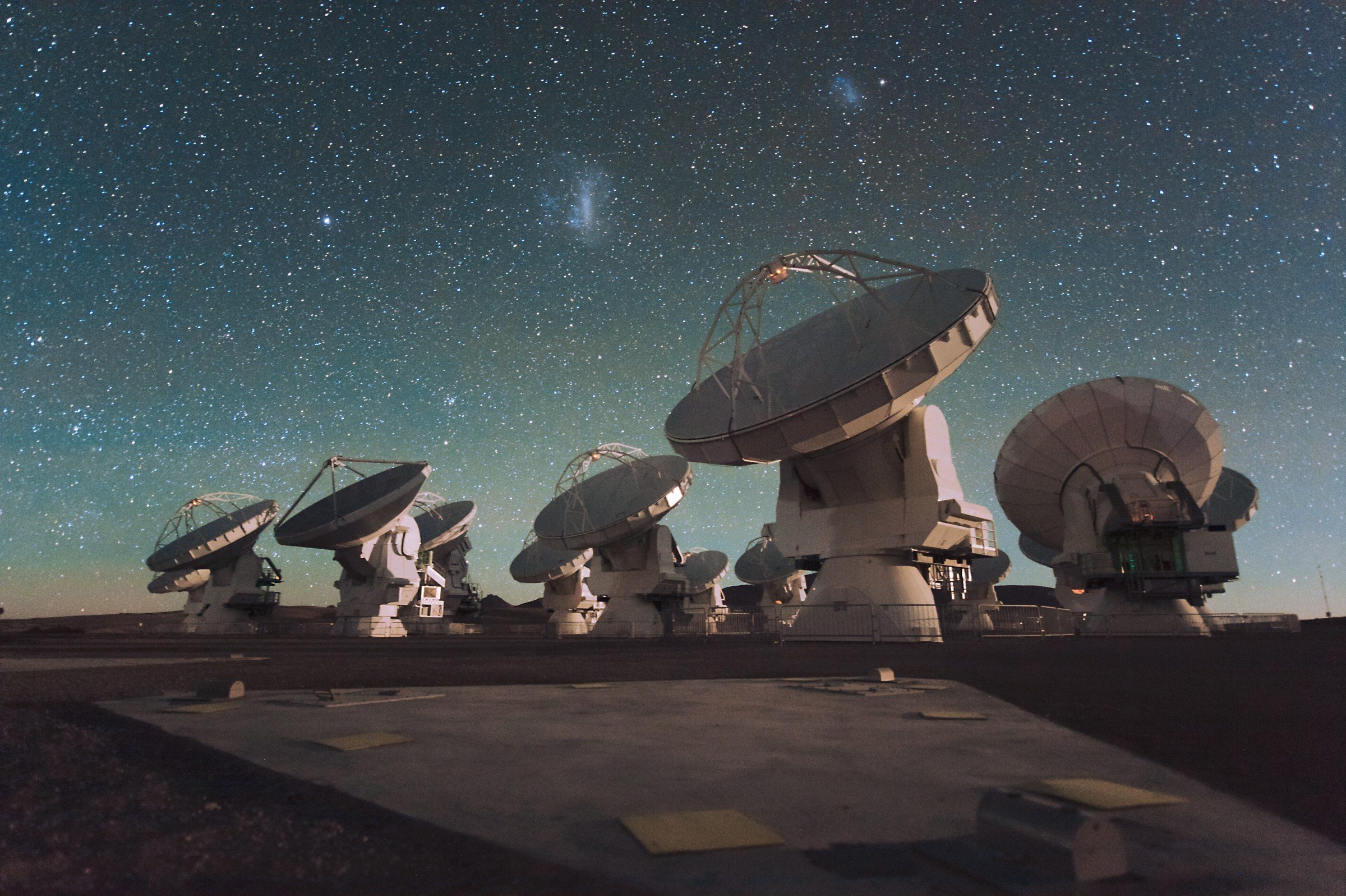
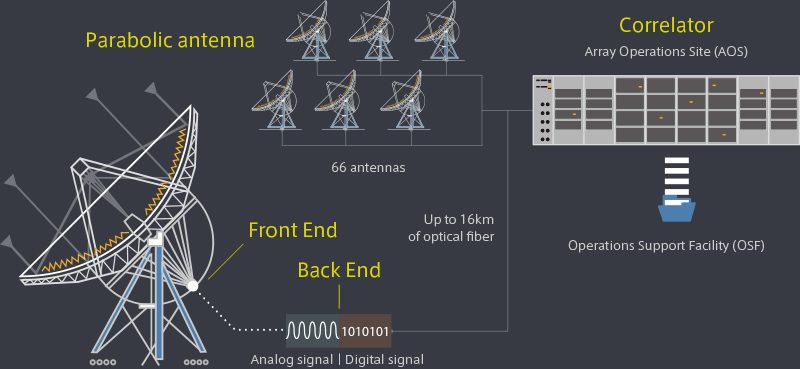
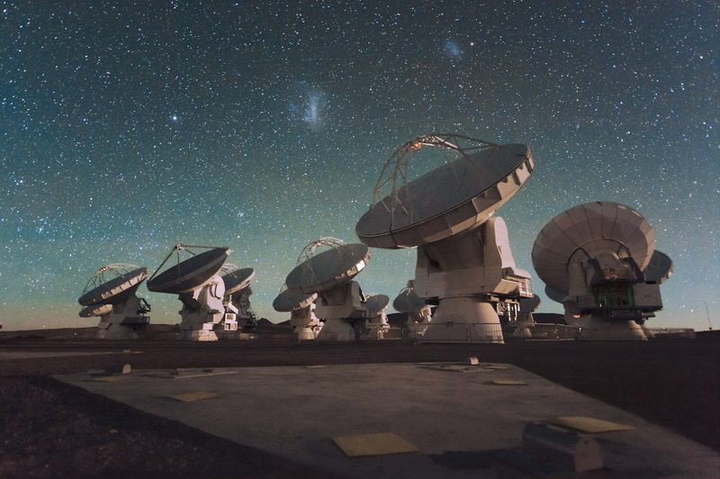
The Atacama Large Millimeter/ Submillimeter Array (ALMA) is a radio interferometer that is located in the Atacama Desert in Chile (altitude ~16,400 ft.). It consists of 66 antennae, creating a synthesized aperture with a diameter of up to 16 km. There are 59 12-m antennae and seven 7-m antennae, each of which has a parabolic dish (cannot deviate from a perfect parabola by more than 20 microns), sub-reflector, and receiver.
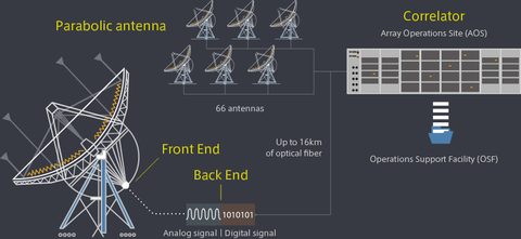
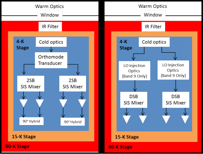
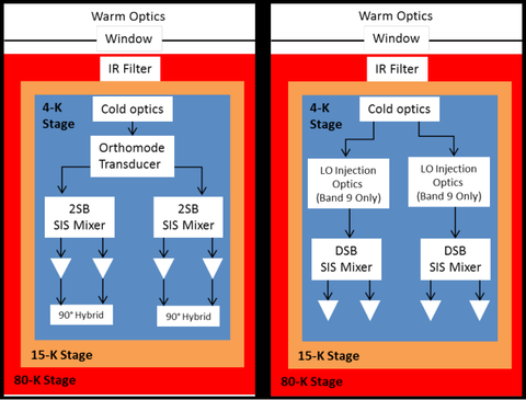
The Front End: Each front end is a cryogenically cooled system that has 10 receiver bands that allow a frequency coverage from 31.3 GHz to 962 GHz. Each band, except bands 1 & 2, is cooled to 4 K and consists of an orthomode transducer (OMT) and either a pair of SIS mixers (bands 3-7) or a single SIS mixer (bands 8-10) that are fed by a 90° hybrid RF coupler and LO couplers. This structure can be seen in Figure 2. This system essentially takes a sky signal and 1) mixes it with a reference frequency generated by a local oscillator (LO), 2) lowers the signal to an intermediate frequency (IF), 3) splits it between its polarizations (using the OMT), then splits it again into an upper and lower sideband (using the SIS mixers), and 4) sends these signals to the back end.
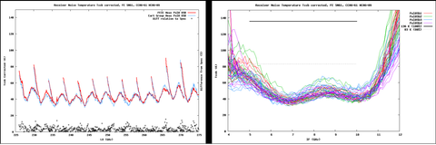
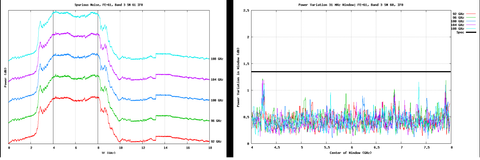
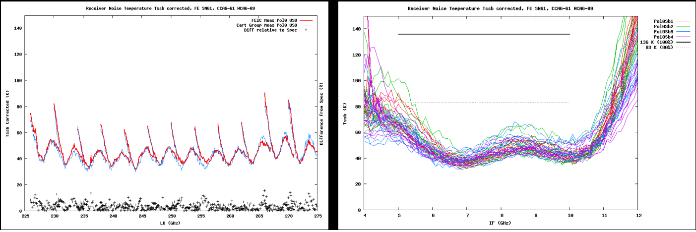
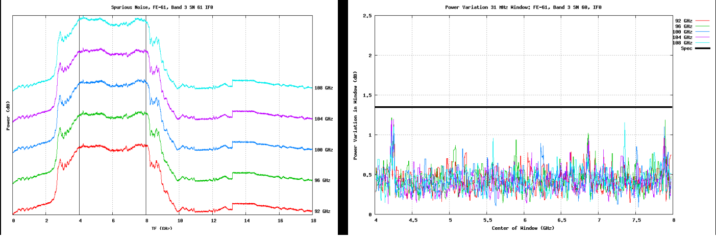
The Test System: The test system compares system outputs to pre-determined specifications for minimal noise in the observations made by the receivers. This system tests noise temperature (noise added to the output from the receiver) and the IF output spectrum (checks for spikes in power over the IF window and the maximum power variation a specified IF range), along with other attributes in the Warm Cartridge Assembly (WCA).
New Modular Library: This library is written in PHP and is used to accept, analyze, and display test data from the Front Ends. This upgrade features a more structured interface that allows flexible database retrieval, universal data structures that allows for simple data manipulation, and an adaptable plotting algorithm.